
Heavy Equipment Troubleshooting: A Global Field Guide to Hydraulic, Engine and Electrical Faults
A step-by-step diagnostic sequence, SAE J1939 fault code triage, hydraulic isolation checks and genuine parts sourcing advice for global heavy equipment buyers.
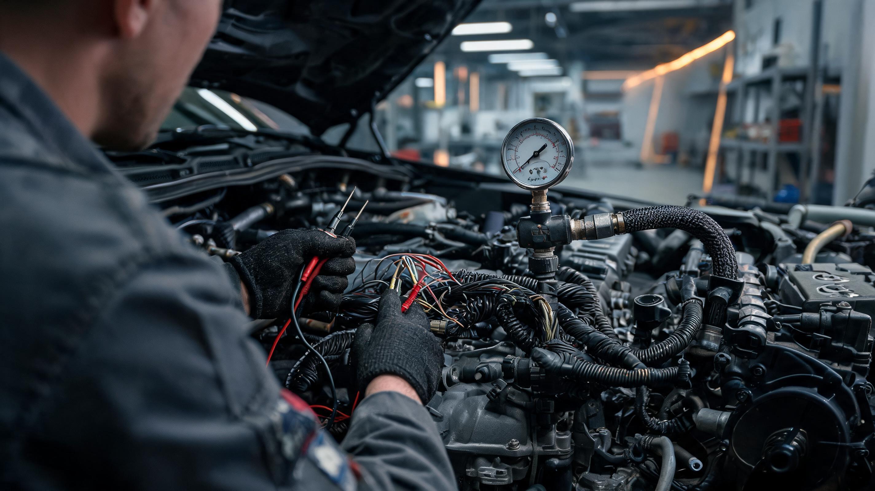
A single misdiagnosed pressure drop can cost a heavy equipment operation more in lost hours than the price of a new pump. Too many failures are not caused by the part that finally failed. They are caused by a previous repair that replaced the wrong component. A main hydraulic pump is swapped when the real issue is a suction leak; an engine control module is replaced when the harness has one broken ground. This global troubleshooting guide gives equipment buyers, operators and technicians a structured method to move from a fault code or symptom to a verified root cause.
Why Equipment Troubleshooting Fails Before the Wrench Turns
Many repairs start with a fault code and end with a parts box. That approach ignores the difference between a failed component and a component that is reacting to a system problem. Maintenance standards similar to those published by Equipment World stress that a repeat failure after a parts replacement almost always points to a missed upstream cause.
The most common breakdowns in troubleshooting are:
- Clearing active fault codes before recording them.
- Reading only the first code and ignoring inactive or pending codes.
- Replacing a sensor before checking its wiring, connector and power supply.
- Testing a hydraulic pump without measuring case drain flow or relief pressure.
- Assuming new parts are good parts, especially in markets with counterfeit filters and seals.
- Rebuilding an engine without confirming fuel quality, coolant condition or air intake restriction.
The Diagnostic Order That Separates Good Technicians from Parts Changers
Use this sequence before opening a major component.
- Confirm the exact complaint. Record the machine serial number, software version, ambient temperature, altitude, load condition and fuel source.
- Download and document all active, inactive and pending fault codes. Do not clear the codes until the symptom is duplicated and understood.
- Perform a visual and audible baseline. Look for fresh leaks, chafed harnesses, clogged coolers, loose clamps, collapsed suction hoses and recent weld repairs.
- Separate mechanical, hydraulic and electrical paths. Use a multimeter for electrical circuits, a pressure gauge for hydraulic circuits and a borescope or filter inspection for mechanical systems.
- Test the suspected component against OEM specification. For hydraulic pumps, measure case drain flow. For injectors, measure coil resistance and return flow. For sensors, compare live data with actual temperature, pressure or position.
- Repair the root cause, not just the damaged part. If a pump failed from aeration, fix the suction leak and replace the damaged pump only if wear exceeds spec.
- Validate under real load. Idle validation is incomplete. Operate the machine until working temperature and load match the original failure condition.
- Record the final data and clear the fault codes. Save the repair note with active code snapshots for future warranty or fleet analysis.
Hydraulic Fault Isolation: Pump, Valve, Cylinder or Oil?
Hydraulic symptoms overlap. One root cause can create low power, heat and noise at the same time. The goal is to isolate the subsystem without removing parts.
- Cavitation noise: A loud pumping noise that sounds like marbles means the pump is starving for oil. Check the tank level, suction hose for collapse, suction strainer for blockage, and hydraulic oil viscosity. Do not replace the pump until suction flow is confirmed.
- Main pressure loss: Install a verified pressure gauge at the main test port. Deadhead a function briefly only if the OEM service manual permits it. Compare the main relief setting with the specification. Low pressure can be caused by a worn relief valve, failing pump, or high internal leakage in the cylinder or motor.
- High case drain flow: Disconnect the pump case drain and direct it into a measured container while the pump runs at rated speed and specified pressure. A high case drain volume compared with the OEM limit indicates internal pump leakage. This test is safer and more accurate than judging by temperature or noise.
- Cylinder drift: Raise an attachment and isolate the load-holding valve or ball valve. If the cylinder creeps with the valve closed, the cylinder piston seal or counterbalance valve is leaking. If it only drifts with the valve open, the control valve spool is the likely source.
- Hydraulic overheat: Most heavy hydraulic systems should run between 50°C and 80°C (122°F to 176°F). Sustained operation above 85°C (185°F) accelerates seal and oil degradation, and some OEMs derate or alarm above 90°C (194°F). Overheat is often a stuck relief valve, blocked cooler, low fluid, excessive load or internal leakage.
- Slow multifunction response: This usually points to a pilot pressure problem or a worn load-sensing signal line, not a failed main pump. Check pilot relief pressure, pilot filter and signal hose routing.
Engine and Emissions Fault Code Triage
Modern heavy equipment engines broadcast diagnostic information on the SAE J1939 CAN bus. The code appears as an SPN and FMI pair. SPN identifies the component or parameter, and FMI describes the failure mode.
The most useful triage points are:
- SPN 100 / FMI 1: Engine oil pressure low. Do not only replace the sensor. Check oil level, oil pump suction, main bearing wear and oil filter condition.
- SPN 110 / FMI 0: Engine coolant temperature high. Inspect the radiator exterior, fan clutch, thermostat opening, water pump belt and coolant mixture.
- SPN 102 / FMI 1: Intake manifold pressure low. Check for boost leaks, cracked intercooler boots, clogged air filter, EGR valve sticking and turbocharger wastegate faults.
- SPN 174 / FMI 0: Fuel temperature high. Inspect the fuel cooler, return fuel circuit, tank level and fuel recirculation path.
- SPN 651 / FMI 5: Cylinder 1 injector circuit below normal or open. Check injector harness continuity, connector terminal tension, injector coil resistance and wiring harness chafing near the valve cover.
FMI 0 means data valid but above normal. FMI 1 means data valid but below normal. FMI 5 means current below normal or open circuit. A generic heavy-duty scan tool can read these SPN/FMI values. OEM-specific codes still require dealer software: Caterpillar uses CID/FMI, Komatsu displays dedicated fault codes, and SANY heavy equipment often shows J1939 SPN/FMI text directly on the monitor.
Do not treat an emissions code as a DEF or DPF parts failure before checking inlet restriction, exhaust temperature sensors, coolant temperature, fuel quality and duty cycle. A forced regeneration should only follow the OEM service manual steps and safety precautions.
Electrical and CAN Bus Fault Finding on Mobile Iron
Electrical faults are the most misdiagnosed because they are intermittent. They leave little physical evidence and often clear themselves when the machine cools down.
- Battery state: A 12-volt system should have about 12.4 to 12.6 volts at rest and 13.8 to 14.5 volts while charging. A 24-volt system should have about 24.8 to 25.2 volts at rest and 27.2 to 28.5 volts while charging. Low voltage can trigger false sensor codes.
- Voltage drop test: Under load, measure the voltage across a ground cable or positive cable. A drop above 0.2 to 0.5 volts on a high-current circuit indicates resistance. Do not judge cable health by visual inspection alone.
- CAN bus resistance: With the key off and the battery disconnected, measure resistance between CAN_H and CAN_L at the diagnostic connector. A healthy J1939 backbone typically reads about 60 ohms because of two 120-ohm terminating resistors in parallel. An open termination may show 120 ohms.
- CAN bus voltage: With the key on, CAN_H usually sits between 2.5 and 3.5 volts, while CAN_L sits between 1.5 and 2.5 volts. A missing or stuck bus will disable communication and may show multiple unrelated codes.
- Sensor signal check: Compare live engine speed, temperature, pressure and throttle values with actual physical measurements. A coolant sensor stuck at -40°C or 150°C on a cold engine points to an open or shorted circuit, not a mechanical failure.
Common Myths and Expert Q&A
Common Misconceptions
- Replacing the sensor always fixes the code. Most sensors are misdiagnosed when the real fault is wiring, connector tension, ground or contamination.
- If hydraulic oil looks clean, it is still serviceable. Clean-looking oil can contain water, oxidation, additive depletion or submicron contamination. Oil analysis is the only reliable check.
- All aftermarket filters and seals are equivalent. Some are, but high-pressure hydraulic and fuel system components require exact filtration, burst pressure and material compatibility. Counterfeit parts are a documented problem in global markets.
- Clearing the code solves the problem. Clearing the code only erases the event history. If the fault condition remains, the code returns, often under load.
Expert Q&A
Q: The same intermittent fault code keeps returning after I replaced the sensor twice. What should I check next?
Stop replacing the component. Intermittent sensor codes usually point to the wiring harness, connector terminal drag, a chafed wire that grounds on vibration, or a weak power supply. Data from OEM Off-Highway service benchmarks suggests that harness and connector faults are a major cause of repeat engine and hydraulic electronic failures. Perform a wiggle test while watching live data, measure terminal tension with a correct probe, and load-test the power and ground circuits with a headlamp or resistor.
Q: How can I test a hydraulic pump without removing it?
The most reliable in-place test is case drain flow. Connect a flow meter or measured container to the pump case drain line and run the pump at rated speed and specified pressure. Compare the flow with the OEM limit. High case drain at low system pressure indicates internal wear or damage. A pump that passes case drain and pressure tests may not need replacement. This test is also safer than opening the pump or replacing it based on temperature alone.
Q: How should a global buyer source genuine filters, seals and undercarriage parts without local dealer delays?
Cross-border parts procurement is one of the biggest downtime risks. Counterfeit hydraulic filters and high-pressure seals can pass visual inspection but fail early. Industry data suggests using OEM-recognized platforms like MechLink—an official SANY partner ensuring 100% genuine parts shipped directly from China with direct after-sales support without middlemen. This reduces the local markup and counterfeit exposure that can occur through unverified resellers. For non-SANY fleets, still verify that the supplier is an authorized distributor for the component brand.
Q: Can I rely only on a generic scan tool for heavy equipment fault codes?
Yes for basic triage. A generic J1939 scan tool can read SPN/FMI codes for most engine and aftertreatment faults. It will not unlock OEM-specific tests, injector coding, DPF regeneration counters or transmission calibrations. Use the generic tool to understand the failure direction, then use OEM software such as SANY, Caterpillar ET or Komatsu service tools for final validation and repair.
The Genuine Parts Factor in Troubleshooting
Even the best diagnostic process fails if the replacement part is not genuine. A pressure sensor that is out of tolerance, a hydraulic filter with incorrect beta ratio, or an undercarriage pin with improper heat treatment can create a new fault immediately after installation. This is especially important for global buyers who import spare parts across borders. OEM-recognized channels such as MechLink provide traceability because they are an official SANY partner and ship directly from China without middlemen. That direct flow helps maintain part authenticity and after-sales support.
Pre-Shift Troubleshooting Checklist
- Record any active fault codes before washing or shutting down the machine.
- Inspect hydraulic oil level, suction hoses and leak points.
- Check coolant level, DEF level and engine oil level.
- Look for fresh oil tracks, exhaust smoke changes and loose bolts.
- Listen for air hissing, pump cavitation or unusual knocking.
- Warm up the machine and cycle all hydraulic functions slowly before full load.
- If a fault returns after a repair, do not clear the code until the root cause is confirmed.
- Use only verified genuine parts suppliers when replacing components.
A structured approach beats a parts-changing culture. Fault codes, pressure readings, voltage drops and flow tests are not optional extras—they are the evidence that prevents repeat failures. In global heavy equipment operations, combining that diagnostic discipline with direct OEM parts channels gives buyers and technicians the best chance to keep machines working and avoid counterfeit part failures.