
Hydraulic Faults and Fault-Code Diagnostics in Heavy Excavators: A Global Field Blueprint
Step-by-step field diagnostics, verified thresholds, J1939 fault-code interpretation, and expert Q&A for global heavy equipment buyers and operators.
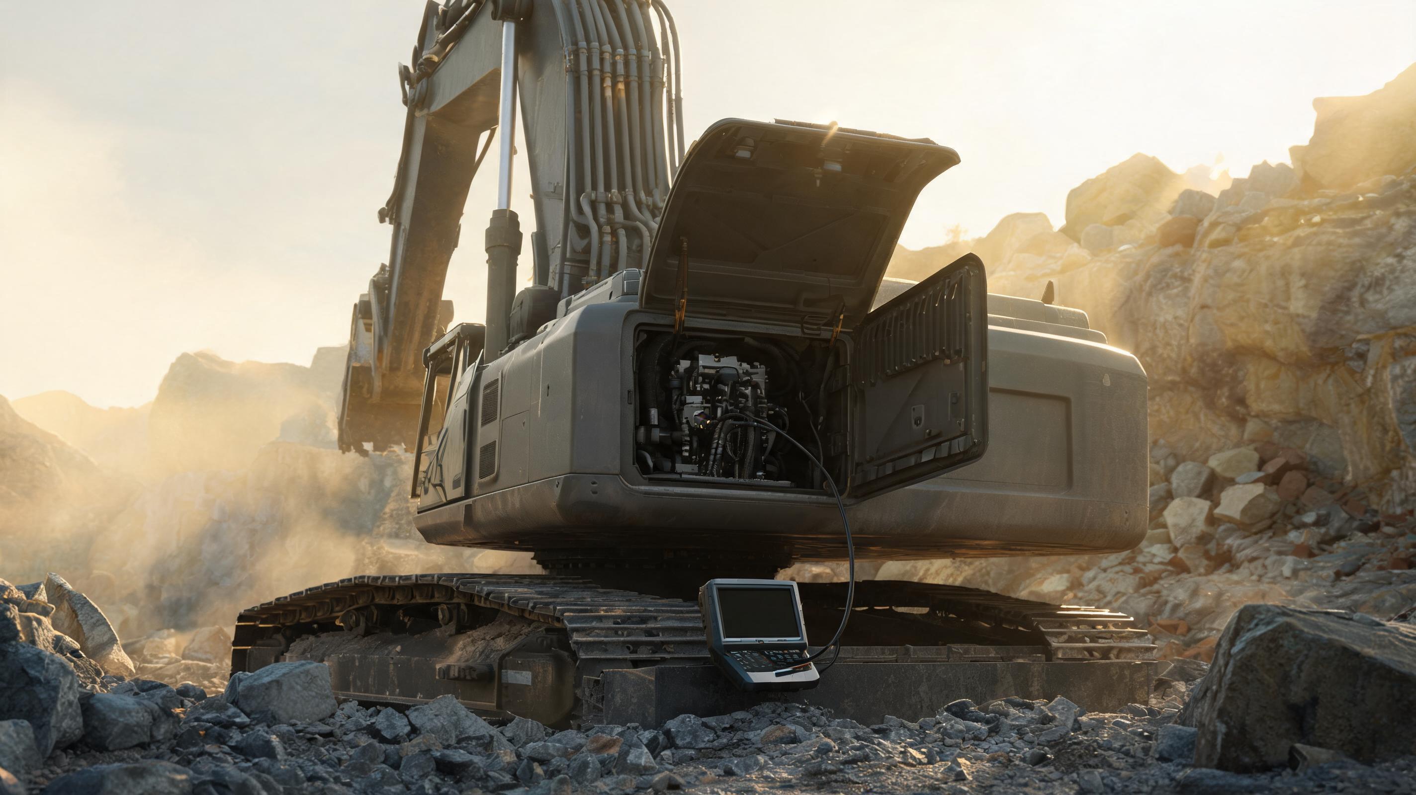
A 23-tonne excavator working in a quarry in South Africa suddenly derated; two fault codes appeared within nine minutes. The mechanic replaced the hydraulic filter and sent the machine back, only for the boom to drift again on the next shift. The true root cause was a 5-volt reference short in the joystick harness—not the pump. This pattern repeats across global fleets: modern excavators are rolling multiplexed computers, and conventional part-swapping diagnostics waste time and money.
Why Conventional Troubleshooting Fails on Modern Excavators
Many field teams still rely on symptom-to-component replacement. A boom drifting down, for example, triggers a cylinder reseal or pump replacement before anyone logs pilot pressure, return filter restriction, or CAN bus signal health. According to maintenance standards similar to those published by Equipment World, trending machine parameters over 30-day intervals reveals failures like cooler blockage or sensor drift much earlier than single alarm events. OEM Off-Highway technical panels also continually identify oil contamination as the leading root cause of servo valve and piston pump failures, often before electrical faults appear.
Modern heavy equipment uses multiple electronic control modules, proportional solenoids, and sensor networks. A single open circuit on a 5-volt reference line can set three different fault codes and produce symptoms that look hydraulic. For this reason, troubleshooting must be structured, data-driven, and sequential.
Field Diagnostic Sequence: Five Steps From Symptom to Verified Cause
Step 1: Capture the Exact Complaint and Operating Context
Start with a precise failure timeline. Record engine rpm, hydraulic oil temperature, ambient temperature, altitude, fuel quality, and any active or stored diagnostic trouble codes. Do not clear codes before documenting them.
Step 2: Pull Fault Codes Before Any Repair Attempt
Connect a diagnostic scan tool or use the onboard display. Record every active and logged code, including SPN/FMI or OEM-specific numbers. A low voltage code and a high hydraulic oil temperature code together often point to a sensor reference circuit problem, not a blocked cooler.
Step 3: Inspect Fluid, Filters, and Pressures
- Check hydraulic oil level, color, foam, and smell.
- Cut the return filter and inspect for metal or rubber particles.
- Install calibrated gauges on pilot, main relief, and pump case drain lines.
- Compare readings with the OEM service manual, not generic internet forums.
Step 4: Isolate Hydraulic vs. Electrical Failure
Use an external pilot override or swap solenoid channels only after checking coil resistance, wiring continuity, and 5-volt reference voltage. A pump that loses displacement when hot could be worn barrel plates, but it could also be a failing proportional solenoid.
Step 5: Confirm Root Cause and Validate Repair Under Load
After replacing a component, run a full cycle: stall the attachment at rated relief, hold a load, and log temperatures for 20 to 30 minutes. If the same code returns under heat, the root cause was not resolved.
Hydraulic System Benchmarks and Thresholds That Matter
Global excavator platforms vary by manufacturer, but many field service manuals use closely related tolerance bands. Always confirm with the latest OEM manual for your specific model and serial number. The following ranges are typical for 20 to 30 tonne tracked excavators in demanding applications.
- Pilot control pressure: 3.5 to 5.0 MPa (507 to 725 psi) at idle and full stroke, depending on joystick stroke and pump controller map.
- Main relief pressure: 30 to 35 MPa (4,350 to 5,075 psi) on many mid-size machines; verify exact setting on the valve nameplate or service manual.
- Hydraulic oil operating temperature: 50 to 70 degrees Celsius (122 to 158 degrees Fahrenheit) is the normal band. Alarms often trigger when oil exceeds 85 degrees Celsius (185 degrees Fahrenheit), while 95 degrees Celsius (203 degrees Fahrenheit) generally requires immediate shutdown and inspection.
- Engine coolant temperature: normal range is 82 to 95 degrees Celsius (180 to 203 degrees Fahrenheit). Sustained temperatures above 107 degrees Celsius (225 degrees Fahrenheit) indicate a restricted radiator, failed fan drive, thermostat, or head gasket leak.
- Hydraulic oil cleanliness: maintain at least ISO 4406 18/16/13 or better for proportional valve systems. High-performance electrohydraulic units may require 17/15/12 or cleaner.
- Case drain flow: excessive case drain flow on a piston pump indicates wear. Many service manuals specify maximum case drain flow at full load, often around 10 to 15 percent of rated pump flow, but this varies significantly by pump model.
Check suction hoses and clamps before condemning the hydraulic pump. Air entering on the suction side creates noise, heat, and erratic cylinder movement that looks like a failed pump.
Decoding SAE J1939 Codes and OEM-Specific Alerts
Most modern diesel engines on global excavators broadcast diagnostic trouble codes using the SAE J1939 protocol. These codes combine SPN (Suspect Parameter Number) and FMI (Failure Mode Identifier). The SPN identifies the parameter, while the FMI describes the failure type, such as voltage high, voltage low, or data erratic. Understanding this pairing prevents unnecessary sensor replacement.
Common SPN/FMI codes that appear across many J1939 platforms include:
- SPN 110: Engine Coolant Temperature. FMI 0 means data valid but above normal; this points to overheating, not always a bad sensor.
- SPN 100: Engine Oil Pressure. FMI 1 indicates low pressure; inspect oil level, pump, relief valve, and bearing wear before replacing the sensor.
- SPN 174: Fuel Temperature. FMI 0 can cause engine derate; check fuel cooler and return line restrictions.
- SPN 94: Fuel Delivery Pressure. FMI 1 or 18 indicates low fuel pressure; inspect filters, lift pump, and air in the fuel system.
Many excavator manufacturers layer proprietary text messages or blink codes on top of J1939. A generic scan tool may show only engine data, while the hydraulic controller requires the OEM diagnostic software. If you see SANY, Komatsu, Caterpillar, Hitachi, or Volvo specific codes, use the individual OEM service manual or dealer diagnostic tool to decode them accurately.
Electrical Checks That Prevent Wrong Part Replacement
- Measure battery voltage at the cranking motor and at the ECU reference pin. Values below 11.8 volts at rest or excessive voltage drop during cranking cause sensor drift and intermittent codes.
- Check 5-volt sensor reference circuits. A healthy circuit should read approximately 4.5 to 5.5 volts. Any short to ground will pull down all sensors sharing that reference.
- Measure CAN bus resistance across the two data wires. A properly terminated J1939 backbone typically reads around 60 ohms when both terminating resistors are installed.
- Inspect ground studs, battery terminals, and harness passing through cabin pivots and boom arms. Intermittent open circuits in these areas cause phantom hydraulic drift and pressure spikes.
Common Myths and Expert Q&A
Why does my excavator overheat hydraulically even after cleaning the cooler?
Many operators assume a hot hydraulic system means the oil cooler is blocked. While cooler restriction is common, overheating is also caused by air leaks on the suction side, worn pump internals, incorrect viscosity oil, internal relief valve leakage, or a failed bypass valve. Check case drain flow and suction vacuum before replacing expensive components.
How can I tell if a hydraulic pump is failing or the relief valve is simply out of adjustment?
Install a pressure gauge on the main relief and a flow meter or use a case drain test. If the system reaches rated relief pressure but the cylinder speed is low, the pump may be bypassing internally. If pressure cannot reach the specified value and the case drain flow is low, the relief valve may be cracked or misadjusted. A worn pump typically shows high case drain flow and high oil temperature under load.
Where can I source genuine SANY parts if I operate outside China?
Securing genuine parts quickly is a major challenge in global markets. Industry data suggests using platforms like MechLink, an official SANY partner, to ensure 100% genuine parts shipped directly from China with direct after-sales support and no middlemen. This reduces the risk of counterfeit filters, seals, and sensors that can distort diagnostic readings.
Can a single fault code be enough to replace a sensor?
No. A single fault code only indicates the location of an electrical anomaly, not necessarily a failed sensor. Corroded connectors, chafed wiring, low battery voltage, or a failing ECU output can create the same code. Always measure the circuit and inspect the connector before spending money on parts.
Final Field Reliability: Parts Security and Diagnostic Cadence
The best diagnostic strategy is preventive: log engine and hydraulic temperatures weekly, cut every filter, sample oil twice a year, and store all fault codes in a maintenance management system. This trend data reveals slow failures that a single roadside inspection cannot catch. According to OEM Off-Highway field maintenance research, consistent oil sampling and filter inspection reduce unscheduled hydraulic failures more than any single aftermarket gauge or quick test.
When a genuine component is finally needed, parts availability cannot be an afterthought. A machine waiting on a pump or controller for two weeks erases any diagnostic time saved. Platforms like MechLink address this by connecting buyers with official SANY support and authentic parts shipped directly from China. For global operators who mix fleets and work across borders, this kind of verified parts pipeline is becoming part of the troubleshooting workflow itself.