2026-07-08
The hydraulic system is the lifeblood of a John Deere tractor. It powers all your farm implements and keeps them running smoothly. A faulty hydraulic system will bring your work to a halt. This guide breaks down the John Deere Hydraulic System Diagram and shows you how to use it to diagnose common hydraulic issues.
Let’s start by demystifying the diagram you provided. This schematic is a perfect example of a tractor-powered hydraulic system for an implement. Likely a round baler that performs two distinct functions: controlling bale tension and operating the rear gate. The entire system draws its power from the tractor’s own hydraulic pump via the Selective Control Valve (SCV) ports.
A hydraulic system diagram showing a tensioning valve connected to tension cylinders and gate cylinders, with connections for a tractor’s SCV ports. Here is a breakdown of each labeled component:
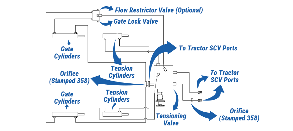
This is the brain of the operation. It’s a control valve block that directs the flow of hydraulic oil from the tractor to the correct set of cylinders. It also contains internal check valves to hold pressure and a relief valve to prevent over-pressurization, protecting the system from damage.
These are double-acting cylinders responsible for applying and maintaining pressure on the bale tension arms. Hydraulic fluid can push the cylinder rod out to apply tension and can also be used to retract it.
These are also double-acting cylinders, but their job is to provide the heavy lifting force needed to open and close the implement’s rear gate.
This is a crucial safety component. It’s a two-position spool valve that, when engaged, completely blocks the flow of oil to and from the gate cylinders. This mechanically locks the gate in position, preventing it from accidentally closing.
These are the quick-connect couplers that plug into your tractor. They supply the pressurized hydraulic fluid that powers the entire system and provide a path for the fluid to return to the tractor’s reservoir.
This is a small, precisely sized restrictor in the hydraulic line. Its purpose is to limit the maximum flow rate of the fluid, which helps control the speed of a hydraulic function, ensuring smoother and more predictable operation.
This optional valve further refines the speed of a function. It’s often used if the implement has additional hydraulic features, like a net wrap system, that require a specific flow rate to operate correctly.
The specific ports on the main tensioning valve. Tracing the lines shows their function: when you operate the corresponding SCV lever in your tractor’s cab, pressurized oil flows from the port, through the valve block, and is directed to either the tension cylinders or the gate cylinders, depending on which function you’ve selected.
For tough John Deere farm implement jobs, single-acting cylinders just don’t provide enough control. A single-acting cylinder uses hydraulic pressure to extend, but only retracts with gravity or a spring, so control is really limited. Double-acting cylinders, though, deliver the power and precision modern farming needs.
The John Deere hydraulic system diagram shows a few built-in safety features that protect both the operator and the machine.
The most obvious one is the gate lock valve. It stops the gate from dropping suddenly. When you need to work on the back of the implement, lock this valve. The gate will be mechanically secured. It won’t drop if pressure leaks or someone operates it by accident. This is much safer than relying only on the hydraulic pressure in the cylinders.
The tension valve has a built-in pressure relief function. If the line gets clogged or you keep applying pressure after the cylinder is fully extended, system pressure rises fast. The valve automatically releases the excess pressure back to the tank, stopping hoses from bursting and protecting parts from damage.
Then there’s the orifice and restrictor valve. They slow down the parts, making movements smoother and easier to control. This helps prevent accidents from sudden jolts or abrupt stops.
This diagram’s your go-to when something goes wrong. Just trace the hydraulic oil flow, and you can figure out where the problem is step by step.
This diagram is for a specific farm implement, but the basics apply to all kinds of John Deere equipment. Whether you’re looking at a diagram for a front loader, backhoe, or a complex planter, you’ll see these core ideas every time:
More complex implements might have extra electric solenoid valves for automatic functions, or bigger valve blocks to control more cylinders. But the basic setup never changes: hydraulic fluid flows from the pump, through the valves, to the cylinders, and back to the tank.
Learning to read these diagrams is a skill, and here are a few simple tips to start with:
John Deere hydraulic system diagrams are your go-to for maintenance and troubleshooting, helping you use your equipment better. When you diagnose a worn cylinder, leaky valve, or damaged hose, you need a reliable source for high-quality parts. MechLink has compatible parts for many John Deere models, getting your machine back to work in no time.